



Overview
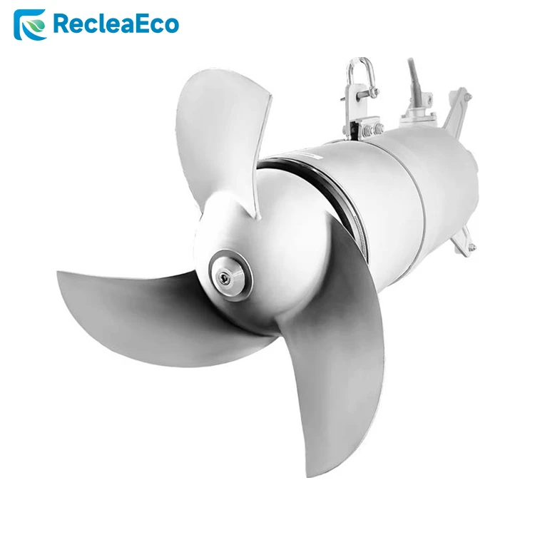
QJB Submersible mixer is used for municipal sewage treatment plant and industrial wastewater treatment plant to produce low tangential flow with force, also can be used for create a flow for circulation, nitrification, denitrification and phosphorus removing.
The submersible mixer features a multi-pole motor and a direct-coupled structure, offering a compact design and ease of maintenance. Its impeller boasts high manufacturing precision and strong thrust.
Features
- Two rows of independent mechanical seal, longer service life.
- Self-cleaning blade, preventing debris from twining or blocking.
- Lowers energy consumption, high aeration rate preventing sedimentation.
- Compact structure, light weight, easy to operate and maintenance, simple installation.
- Class F insulation of motor winding, motor protection grade IP68, imported permanent lubricated maintenance-free bearings, chamber leakage detection, motor winding overheating protection.
Working Conditions
Liquid temperature: ≤ 40℃
PH: 5~9
Liquid density: ≤1150kg/m3
Max working depth: 20m
Parameters
|
Model |
Power (kW) |
Current (A) |
Impeller (mm) |
Speed (r/min) |
Thrust (N) |
Weight (KG) |
Installation System |
|
QJB0.85/8-260/3-740C |
0.85 |
4 |
260 |
740 |
180 |
55 |
System I(II) |
|
QJB1.5/6-260/3-960C |
1.5 |
4 |
260 |
960 |
260 |
55 |
System I(II) |
|
QJB2.2/8-320/3-740C |
2.2 |
8 |
320 |
740 |
580 |
110 |
System II |
|
QJB4/6-320/3-960C |
4 |
12 |
320 |
960 |
690 |
115 |
System II |
|
QJB0.37/6-220/3-960S |
0.37 |
1.3 |
220 |
960 |
138 |
45 |
System I(II) |
|
QJB0.55/4-220/3-1480S |
0.55 |
1.6 |
220 |
1480 |
145 |
45 |
System I(II) |
|
QJB0.85/8-260/3-740S |
0.85 |
4 |
260 |
740 |
180 |
55 |
System I(II) |
|
QJB1.5/6 260/3-960S |
1.5 |
4 |
260 |
960 |
260 |
55 |
System I(II) |
|
QJB2.2/8-320/3-740S |
2.2 |
8 |
320 |
740 |
580 |
110 |
System II |
|
QJB4/6-320/3-960S |
4 |
12 |
320 |
960 |
690 |
115 |
System II |
|
QJB1.5/8-400/3-740S |
1.5 |
5.8 |
400 |
740 |
600 |
100 |
System II |
|
QJB2.5/8- 400/3-740S |
2.5 |
9 |
400 |
740 |
800 |
100 |
System II |
|
QJB3/8-400/3-740S |
3 |
11 |
400 |
740 |
920 |
100 |
System II |
|
QJB4/6-400/3-960S |
4 |
12 |
400 |
960 |
1200 |
100 |
System II |
|
QJB4/12-620/3-480S |
4 |
14.2 |
620 |
480 |
1400 |
184 |
System III |
|
QJB5/12-620/3-480S |
5 |
18.2 |
620 |
480 |
1800 |
184 |
System III |
|
QJB7.5/12-620/3-480S |
7.5 |
28 |
620 |
480 |
2600 |
229 |
System III |
|
QJB10/12-620/3-480S |
10 |
32 |
620 |
480 |
3300 |
229 |
System III |
|
QJB15/12-620/3-480S |
15 |
43 |
620 |
480 |
4000 |
260 |
System III |
|
QJB18.5/12-620/3-480S |
18.5 |
51 |
620 |
480 |
4400 |
276 |
System III |
|
QJB22/12-620/3-480S |
22 |
60 |
620 |
480 |
5300 |
290 |
System III |
The above mixer parameters are obtained under the test of voltage of 380V and frequency of 50Hz.
Reference For Model Selection
The selection of a submersible mixer is a relatively complex task, and the correctness of the selection plan directly affects the normal use of the equipment. The principle of selection is to ensure that the mixer can fully perform its mixing function within the appropriate volume, and this standard is generally determined by flow velocity. According to the different process requirements of wastewater treatment plants, the optimal flow velocity should be maintained between 0.15 and 0.3 m/s.
Before selecting a model, the following factors should be determined:
1. The application site of the submersible mixer, such as whether it is a sludge tank or a biochemical tank.
2. The parameters of the medium, such as suspended solids content, temperature, pH value, etc.
3. The shape and depth of the tank, as well as the installation method.
Additionally, energy-saving considerations should be considered, as they will impact the user's future operating costs. The submersible mixer flow field diagram can also be referenced.
Special Reminders:
1. The submersible mixer must be fully submerged in water to operate.
2. It is prohibited to operate in flammable, explosive, highly corrosive, or high-temperature environments.
3. The minimum submersion depth for the submersible mixer is 900 mm.
Dimensions Chart

|
Model |
L |
øD1 |
øD2 |
Hole size for installation |
|
(mm) |
(mm) |
(mm) |
(mm) |
|
|
QJB0.37/6-220/3-960S |
500 |
250 |
300 |
600x600 |
|
QJB0.55/4-220/3-1480S |
500 |
250 |
300 |
600x600 |
|
QJB0.85/8-260/3-740S |
560 |
280 |
350 |
800x800 |
|
QJB1.5/6 260/3-960S |
560 |
280 |
350 |
800x800 |
|
QJB2.2/8-320/3-740S |
700 |
350 |
440 |
1000x1000 |
|
QJB4/6-320/3-960S |
700 |
350 |
440 |
1000x1000 |
|
QJB1.5/8-400/3-740S |
700 |
420 |
500 |
1000x1000 |
|
QJB2.5/8- 400/3-740S |
700 |
420 |
500 |
1000x1000 |
|
QJB3/8-400/3-740S |
700 |
420 |
500 |
1000x1000 |
|
QJB4/6-400/3-960S |
700 |
420 |
500 |
1000x1000 |
|
QJB4/12-620/3-480S |
950 |
630 |
720 |
1200x1200 |
|
QJB5/12-620/3-480S |
950 |
630 |
720 |
1200x1200 |
|
QJB7.5/12-620/3-480S |
980 |
630 |
720 |
1500x1500 |
|
QJB10/12-620/3-480S |
980 |
630 |
720 |
1500x1500 |
|
QJB15/12-620/3-480S |
1100 |
630 |
720 |
1500x1500 |
|
QJB18.5/12-620/3-480S |
1100 |
630 |
720 |
1500x1500 |
|
QJB22/12-620/3-480S |
1100 |
630 |
720 |
1500x1500 |
The model with an impeller diameter of 620mm can be equipped with a flow deflector/dome. The impeller diameters of 320mm, and 400mm are equipped with a flow deflector by default. Please contact our company for specific requirements.
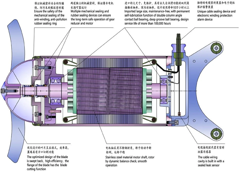
Structure Diagram
Flow Field Diagram

| QJB0.37/6-220/3-960S QJB0.55/4-220/3-1480S | QJB0.85/8-260/3-740S QJB1.5/6-260/3-960S |

| QJB1.5/8-400/3-740S | QJB2.2/8-320/3-740S QJB2.2/8-400/3-740S |

| QJB2.5/8-400/3-740S QJB4/6-320/3-960S | QJB3/8-400/3-740S |

| QJB4/6-400/3-960S | QJB4/12-620/3-480S |

| QJB5/12-620/3-480S | QJB7.5/12-620/3-480S |

| QJB10/12-620/3-480S | QJB15/12-620/3-480S |

| QJB18.5/12-620/3-480 | QJB22/12-620/3-480S |
Installation System
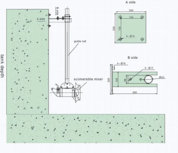
Installation system Ⅰ
1. Tank depth H <3m
2. Direction can be adjusted in horizontal and vertical
3. Depth of guide rod is 3 meters
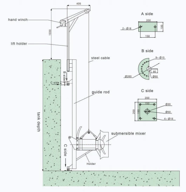
Installation system Ⅱ
1. When depth> 4m, need add another side support on guide rod.
2. The connection shall be expansion bolt between side support & tank wall, holder & tank bottom.
3. Please inform tank depth when you put order to us.
Installation Ⅲ
1. When depth> 4m, need add another side support on guide rod.
2. The connection shall be expansion bolt between side support & tank wall, holder & tank bottom.
3. Please inform tank depth when you put order to us.

Project Sites

Hot Tags: submersible mixer, China submersible mixer manufacturers, suppliers, factory, Hyperboloid Mixer, Cyclone Aerator, Roots Blower, Microscreen Drum Filter, wastewater mixer, Vertical Agitator


